 Forma3D
Edit STL files
All the mesh-editing tools in Forma3D — selection, Boolean, cut, repair, and export.
Need to print a model bigger than your build plate, or in two materials? In Forma3D you can paint the faces of a mesh to mark where it should separate, then generate matching peg-and-socket joints in the same pass.
Tutorial updated October 11, 2026 · iOS 17 or later · Screenshots show Forma3D running on Mac. The same tools are available on iPhone and iPad; layouts may differ.
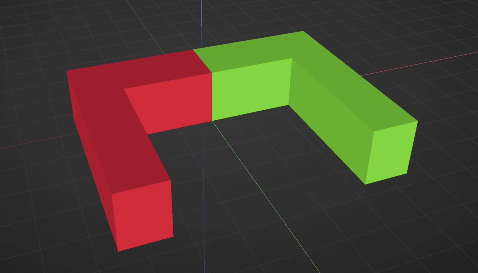
Select the arch in Object mode and open the Paint tool. Paint one side of the model — here the left half goes red. Every face that should end up in that part needs the same color; faces left unpainted stay in the default region.
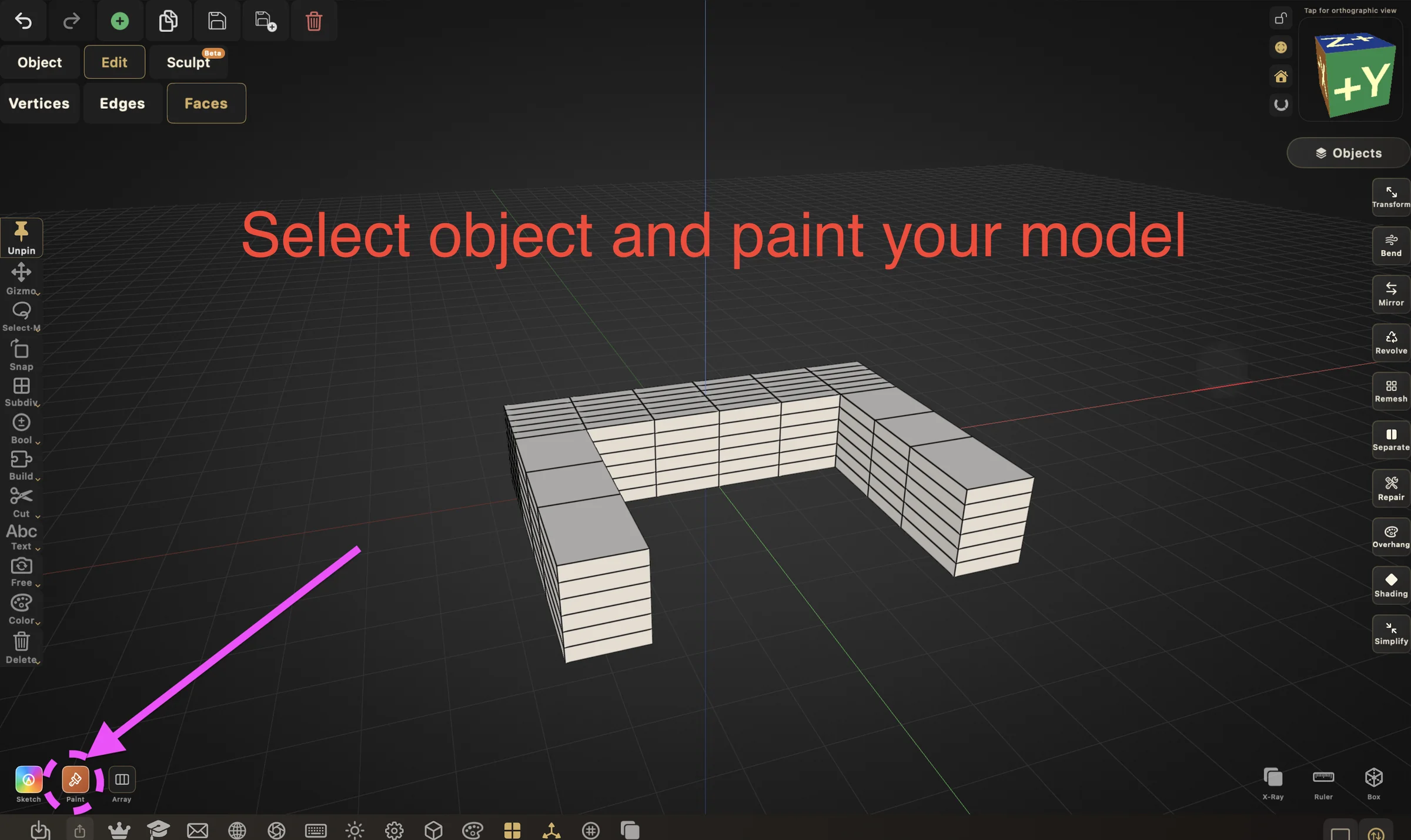
Paint the other half green so the whole surface is covered by exactly two color regions meeting at a clean boundary. These colors are only labels for the separation — they don't have to match your filament choices, and the "Target parts" count in the next panel groups small stray islands into the surrounding region, so a speck of wrong color won't spawn an unwanted extra part.
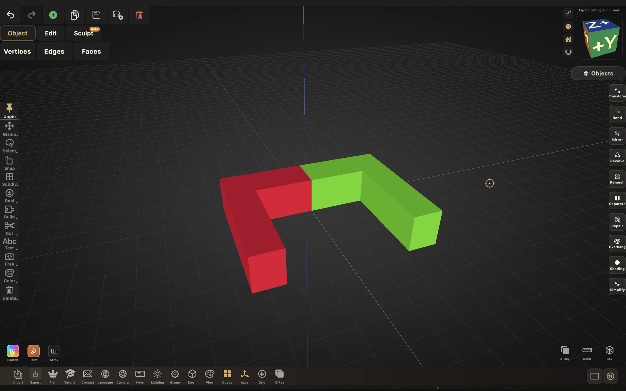
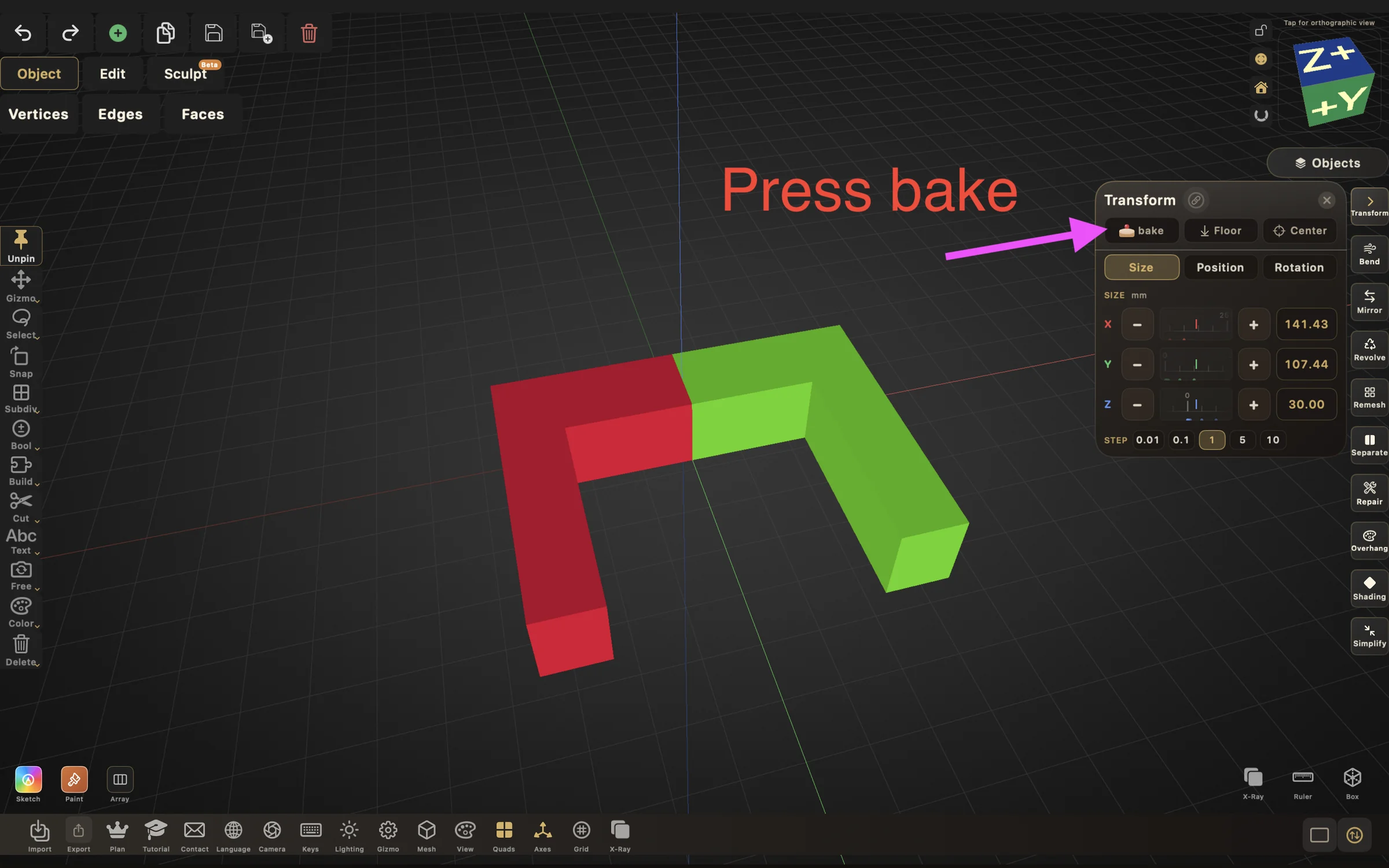
If you scaled or rotated the object after importing it, open Transform and press Bake. Bake writes the current scale and rotation into the mesh's vertices and resets the node's transform, so the joints are generated on the real geometry rather than a scaled node. The visible shape doesn't change.
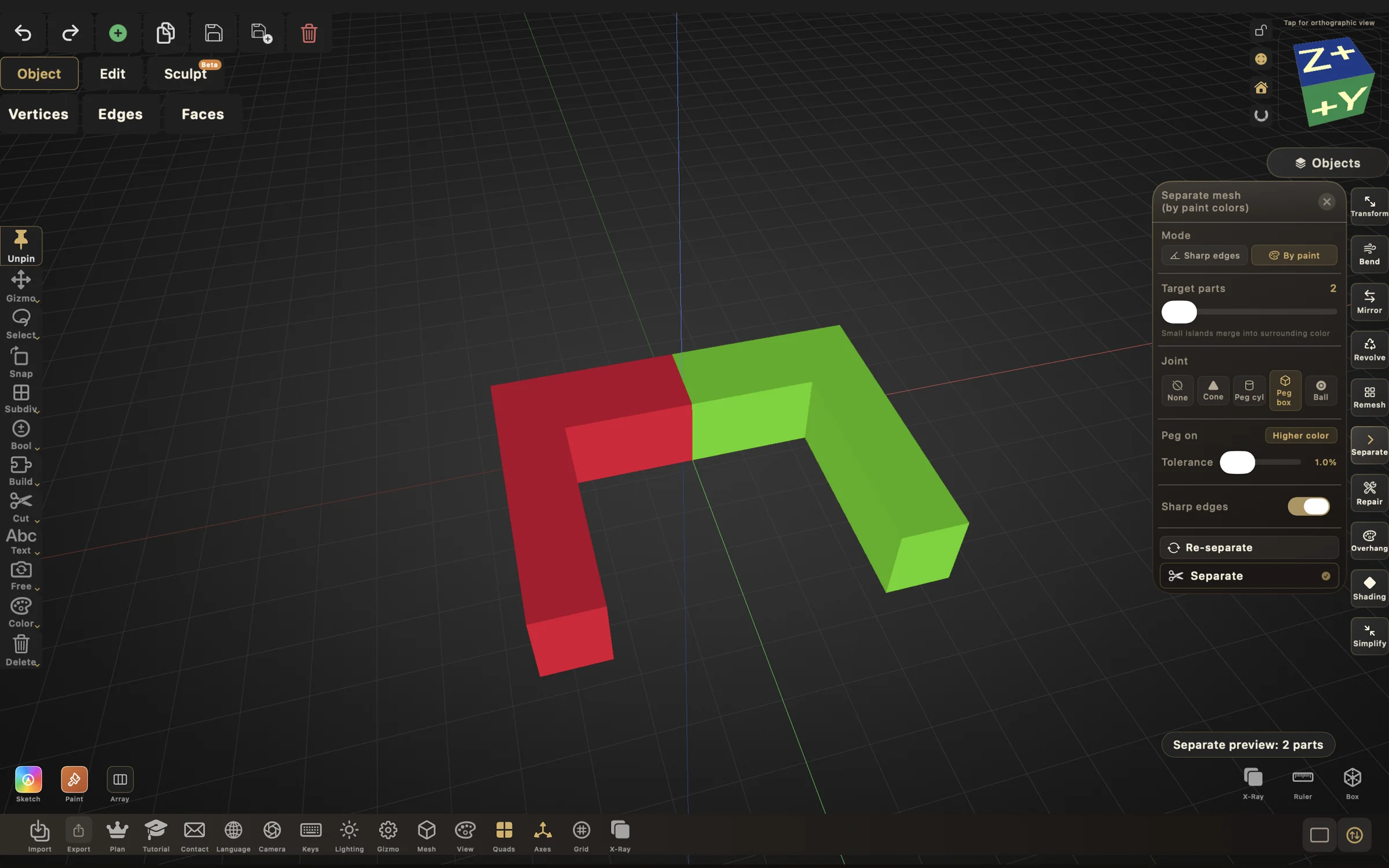
Open Separate and set the mode to By paint. For this arch the settings are: Target parts 2, joint Peg box (the square tongue-and-groove), Peg on Higher color, Tolerance 1.0% (a percentage of the joint size, not millimeters), and Sharp edges on. "Peg on" picks which painted color region carries the peg — Higher color or Lower color — so flip it if you want the peg on the other half. Press Re-separate to refresh the preview while tuning, and Separate to apply.
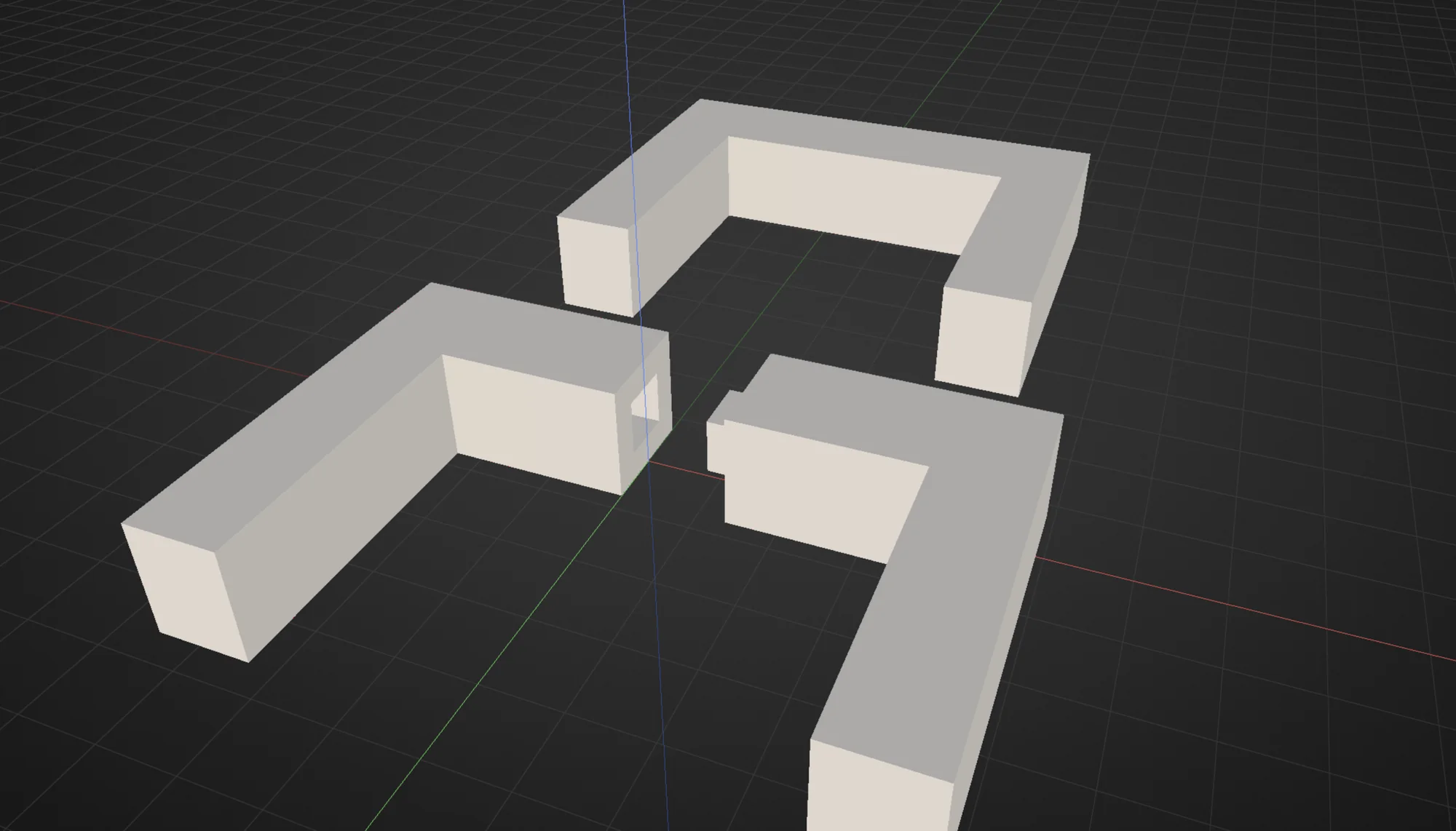
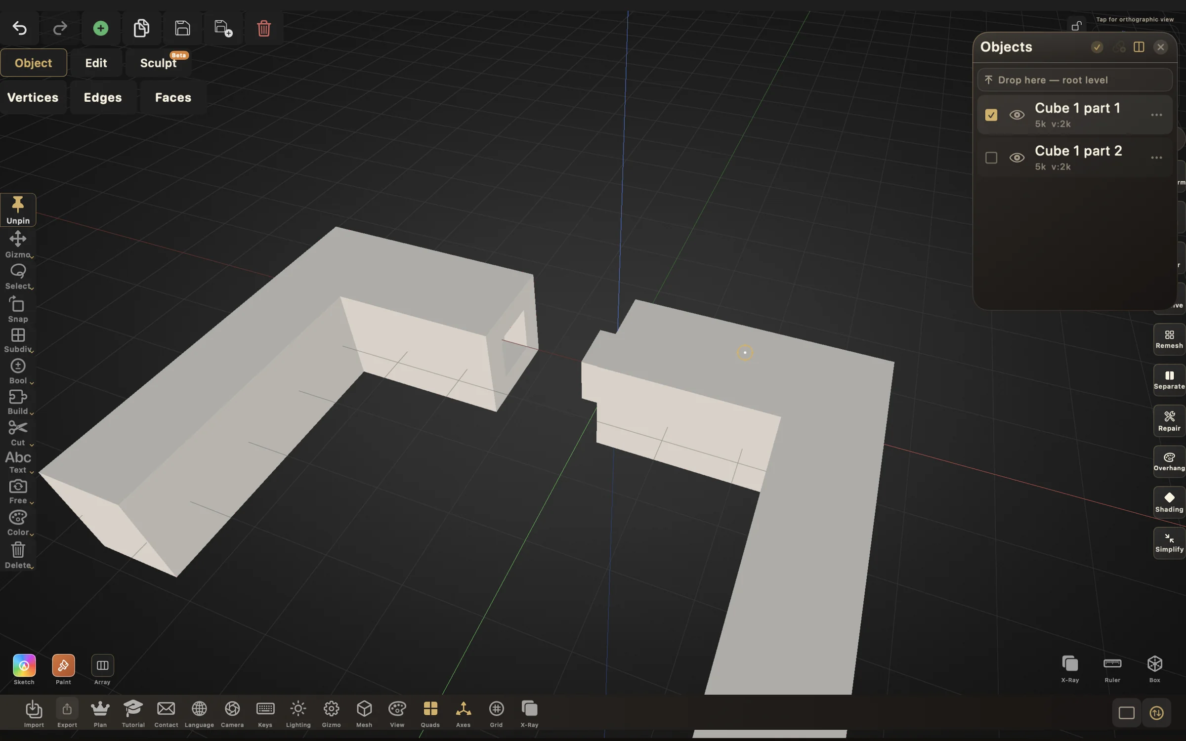
Press Separate. The Objects list now shows two parts instead of one. Move the pieces apart slightly to check the joint: one part carries a square peg, the other the matching socket. The parts in this screenshot were moved apart by hand to show the interface — nothing here guarantees a printable fit, so verify the joint on your printer before committing to a long print.
Select a part, open Export → Export STL, and choose Selected objects so only that piece is written. Repeat with a different file name for the second half. STL carries no color; export 3MF instead if you want the face colors preserved. In your slicer, check orientation, seam placement, wall thickness around the joint, and whether the peg needs supports — a small test print of just the joint region is a cheap sanity check.
A line cut slices the model along a straight screen-space plane. "By paint" follows the face regions you painted, so the boundary can run anywhere across the surface — useful when the split shouldn't be straight.
Yes — no painting needed for a single straight cut. Switch to Edit mode, select the edge component, tap one edge where the cut should go, then press Loop Select → Select Loop to select the full ring. Press Split and choose "Split by Edges" for a clean cut into two objects, or "Separate with Joint" to open the same joint workflow covered here.
No — Tolerance is a percentage relative to the joint's size, not an absolute millimeter gap. 1.0% is a starting point; every printer and material fits differently, so test the joint before printing the full part.
Yes — paint as many regions as you need. Target parts controls how the painted regions are grouped into final objects, which matters when a color appears as several disconnected islands.
All the mesh-editing tools in Forma3D — selection, Boolean, cut, repair, and export.
Keep face colors through the export for multi-material slicer workflows.
Paint faces, then clean up color islands and merge similar colors — the paint-cleanup companion to splitting by color.
Getting edited models from iPhone and iPad to the printer.
Open the STL in Forma3D, then either use the cut tools, select an edge loop and Split by Edges, or paint regions and Separate with joints — then export each piece.
Usually yes. Add alignment joints or plan for glue surfaces; Forma3D's Constructor workflow supports print-fit joints and tolerance settings for reassembly.
Yes. Import, cut, separate, and export all run on-device — no desktop slicer or editor is needed.